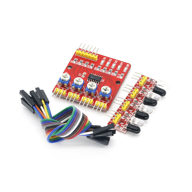
4-way Infrared Tracking Sensor Module Infrared Detection Black White Line Identification Car Obstacle Avoidance ModuleItem NO.: 4-way infrared tracking
-
Customized Requirements
- Quantity
-

-
- Product Name: 4-way Infrared Tracking Sensor Module Infrared Detection Black White Line Identification Car Obstacle Avoidance Module
- Item NO.: 4-way infrared tracking
- Weight: 0.1 kg = 0.2205 lb = 3.5274 oz
- Category: Other Electronic Accessories > Intelligent Car Accessories
- Tag: 4-way , Infrared Tracking Sensor Module , Infrared Detection Black White Line , Identification Car Obstacle Avoidance Module
- Creation Time: 2024-03-28
4-way Infrared Tracking Sensor Module
Module Description:
This module is a solution to provide a multi-purpose infrared detection system for automatic mechanical devices such as intelligent cars and robots. The sensor module has strong adaptability to environmental light. It has a pair of infrared transmitting and receiving tubes. The transmitting tube emits infrared rays of a certain frequency. When the detection direction encounters obstacles (reflective surfaces), the infrared rays are reflected back and received by the receiving tube. After being processed by the comparator circuit, the signal output interface outputs a digital signal (a low-level signal). The detection distance can be adjusted by the potentiometer knob, The effective distance range is 2~60cm, and the working voltage is 3.3V-5V. The detection range of the sensor can be adjusted through a potentiometer, and it has the characteristics of small interference, easy assembly, easy use, etc. It can be widely used in robot obstacle avoidance, obstacle avoidance car, pipeline counting, black and white line tracking and many other occasions.
Module Function Introduction:
The infrared transmitting tube of each sensor continuously emits infrared rays. When the infrared rays emitted are not reflected back or are reflected back but not strong enough, the infrared receiving tube is always in the off state. At this time, the TTL output terminal of the module is at high level, and the corresponding indicating diode is always in the off state; When the detected object appears in the detection range, the infrared ray is reflected back and strong enough, and the infrared receiver tube is connected. At this time, the TTL output terminal of the module is low level, and the indicator diode is lit.
Module Parameters:
1. Working voltage: DC 3.3V-5V
2. Working current: Try to select power supply above 1A
3. Working temperature: - 10 ℃ - + 50 ℃
4. Mounting hole diameter: M3 screw
5. Detection distance: 1mm to 60 cm, adjustable. The closer the distance is, the more stable the performance will be. The white reflection distance is the farthest.
6. Output interface: 6-wire interface (1234 is 4-channel signal output terminal,+is positive power supply, - is negative power supply, that is, ground wire)
7. Output signal: TTL level (it can be directly connected to the I/0 signal of the microcontroller. When the infrared light reflected by the sensor is sensed, the red indicator light will be on and the low level will be output; when there is no infrared light, the indicator light will not be on and the high level will be output.)
Module Application:
1. Smart car or robot line finding (including black line and white line) is also called tracking.
2. The smart car avoids cliffs and falls.
3. Smart car avoiding obstacles
4. It can be applied to other automatic photoelectric reflection applications.
Matters Needing Attention:
1. When using this module, avoid direct sunlight from the probe. The light interferes with the module.
2. The sensitivity adjustment shall not be too high, which may cause false triggering.
3. At the critical value, the LED will be slightly lit, which is not triggered. At this time, the output is high.
1. Test:
Test probe: remove all objects in front of the probe, and the probe should not point in the direction of sunlight. Connect the probe board to the power supply and measure the voltage at the most output terminal with a multimeter. The voltage should be about 1 volt at this time. Block the probe with white paper. The voltage at the output terminal measured with a multimeter should be close to the power supply voltage. Test the middle detection board: connect the tested probe to the input terminal as marked on the board, remove all objects in front of the probe, and the probe should not point in the direction of sunlight. Connect the middle detection board to the power supply, and then measure the output terminal with a multimeter. At this time, the voltage output from the output terminal should be close to the power supply voltage. Use white paper to block the probe, and the voltage measured by the multimeter at the output terminal should be close to 0 volts, The detection distance can be changed by adjusting the potentiometer of the channel.
2. Adjustment:
When the module detects the front obstacle signal, the green indicator on the circuit board lights up at the level, and the OUT port continuously outputs low level signals. The module detects a distance of 2~30cm and a detection angle of 35 °. The detection distance can be adjusted by the potentiometer. Adjust the potentiometer clockwise to increase the detection distance; Adjust the potentiometer counterclockwise to detect the decrease of distance.
Module Wiring Instructions:
1. DO1 -- 1 channel TTL level output
2. DO2 -- 2-way TTL level output
3. DO3 --- 3-channel TTL level output
4. DO4 -- 4-channel TTL level output
5. GND -- Connected to power cathode
6. VCC -- Connected to the positive pole of power supply
Delivery List:
1. 1 main control board
2. 4 probes
3. 18 DuPont lines


You May Also Like
Recently Viewed
- Contact Us
Email:auto@i-emind.com
WhatsAPP:+86 15359446863
Wechat:+86 15359446863
Tel:+86 15359446863
- Company Info
- About Us
- User Center
- Forget Password My Orders Tracking Order My Account Register
- Payment & Shipping
- Locations We Ship To Shipping Methods Payment Methods
- Company Policies
- Return Policy Privacy Policy Terms of Use


Customer Reviews