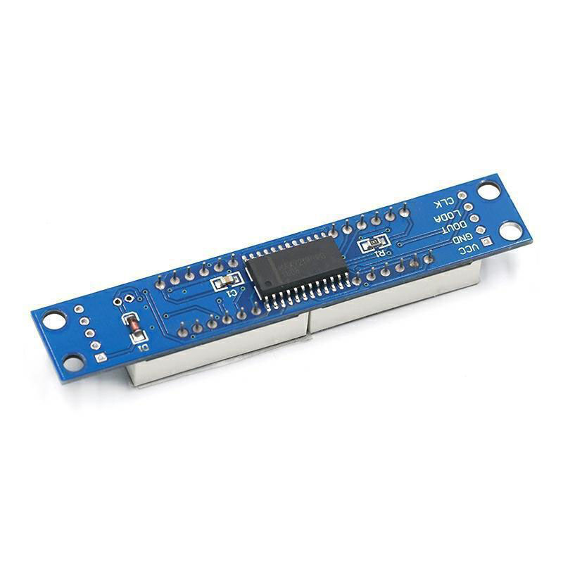
MAX7219 8-Bit Digital Tube Display Module LED Control Module Supports Cascade With Pin ArrangementItem NO.: 8Tubes-MAX7219
-
Customized Requirements
- Quantity
-

-
- Product Name: MAX7219 8-Bit Digital Tube Display Module LED Control Module Supports Cascade With Pin Arrangement
- Item NO.: 8Tubes-MAX7219
- Weight: 0.1 kg = 0.2205 lb = 3.5274 oz
- Category: Electronic Modules > Display Module
- Tag: MAX7219 , 8-Bit Digital Tube Display Module , LED Control Module , Supports Cascade
- Creation Time: 2024-04-17
8-Bit Digital Tube Display Module MAX7219
Product Information:
MAX7219 is an integrated serial input/output common cathode display driver. It connects the microprocessor with 8-digit 7-segment digital LED display, and can also connect the bar graph display or 64 independent LEDs. It includes an on-chip B-type BCD encoder, multiple scan circuit, segment word driver, and an 8 * 8 static RAM to store each data. Only one external register is used to set the segment current of each LED.
A convenient four-wire serial interface can connect all general-purpose microprocessors. Each data can be addressed without overwriting all displays when updating. MAX7219 also allows users to choose whether to encode or not to encode each data.
The whole equipment includes a 150 μ A's low-power off mode, analog and digital brightness control, a scan limit register allows users to display 1-8 bits of data, and a detection mode that allows all LEDs to glow.
You only need 3 IO ports to drive an 8-bit digital tube! There is no flicker when the nixie tube is displayed! Support cascading!
The digital tube is connected to the PCB board with a 2.54mm spacing circular hole row of pins, making it easy to replace the digital tube!
The four corners of the PCB board are fixed with copper studs, which can effectively prevent accidents such as short circuits from occurring!
The digital tube is 0.36 inch 4-in one common cathode digital tube
This module is compatible with a 5V/3.3V microcontroller (51/AVR/STM32.......)
Wiring Instructions:
●VCC→5V
●GND→GND
●DIN →P00
●CS →P01
●CLK→P02
Matters Needing Attention:
1. Never connect VCC and GND in the opposite direction to avoid burning the chip
2. The P0 port of the 51 microcontroller needs to be connected to a pull-up resistor. If your microcontroller is not connected to a pull-up resistor, you can connect the data cable to another port
Shipping List:
1. MAX7219 digital tube display module 1
2. Straight row needle 5P * 1 bent row needle 5P * 1


You May Also Like
Recently Viewed
- Contact Us
Email:auto@i-emind.com
WhatsAPP:+86 15359446863
Wechat:+86 15359446863
Tel:+86 15359446863
- Company Info
- About Us
- User Center
- Forget Password My Orders Tracking Order My Account Register
- Payment & Shipping
- Locations We Ship To Shipping Methods Payment Methods
- Company Policies
- Return Policy Privacy Policy Terms of Use


Customer Reviews